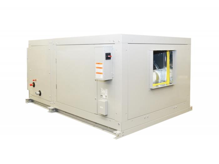
Central Station Air Handlers TAC, TAF, TAH
Overview
Indoor and Outdoor – Heating, Cooling and Ventilation Units
Features
- 14 Models
- Up to 6” Total Static Pressure
- Single Wall Heavy Gauge Galvanized Cabinet
- Efficient Forward Curved Blower
- Up to 64,000 CFM
- Internal Motor
- Up to 100 HP
- ETL Certification
- Horizontal and Vertical Cabinet Styles
- External Electrical Box Mounted to Cabinet
- Extended Grease Lines with External Access
- Stainless Steel Drain Pan on All Cooling Coils
Options
- Double Wall Cabinet with 2” Mineral Wool Insulation
- Outdoor Cabinet
- Internal Vibration Isolators
- Airfoil (Up to 8” Total Static Pressure)
- Disconnect Switch
- Flat Filter
- Angle Filters
- Mixing Box
- Dampers
Specifications TAC, TAF, TAH – Central Station Air Handlers
Application:
- Indoor and Outdoor – Heating, Cooling and Ventilation Units
Electrical:
- 115/1/60
- 208-230/1/60
- 208-230/3/60
- 460/1/60
- 460/3/60
- 575/3/60
Service Parts:
Search for TAC Parts In The Service Parts Database
Search for TAF Parts In The Service Parts Database
Search for TAH Parts In The Service Parts Database
Email Our Service Parts Specialists
Product Specialist:
ahu@t-rp.com
1-844-893-3222 ext. 527
Troubleshooting:
troubleshooting@t-rp.com
1-844-893-3222 ext. 529
BLOWER COMPONENTS
Features a new advanced dynamic design blower section
- high efficiency fan performance
- fans tested per amca code no. 210
- minimum fan tip speeds
- class ii construction
The air handler blower section is a matched assembly combining advanced engineering techniques with the finest materials available. Forward-curved centrifugal fans were designed specifically to operate at low tip-speeds with minimum power consumption. To meet the low noise level requirements of comfort air conditioning, fan outlet velocities have been reduced without sacrificing good fan performance. Blowers are fully performance tested and certified in accordance with DIN, ISO, BS and AMCA 210 standards. Blowers are rated for CLASS II operation and have bearings selected to guarantee a minimum L50 life time of 200,000 hours. The fan section is complete with a rugged drive assembly. The heavy duty motor base is designed for quick and simple belt adjustment. All drives are furnished with matched V-belts.
EXCLUSIVE STEEL FRAME CONSTRUCTION
Sectionalized construction provides complete flexibility of unit arrangements with each individual section structurally designed to provide the absolute maximum in unit strength and rigidity. All static and dynamic forces are directly transmitted to the unit framework. The blowers are supported entirely by rigid frame members, eliminating all dynamic forces from the casing panel. Optional internal blower isolators are also available on all models. For maximum durability, the entire cabinet assembly is fabricated of continuous galvanized steel. This heavy protective finish is maintained intact, completely undisturbed and is complimented with the use of corrosion resistant permanent fasteners. The positive fastening principle of a permanent fastener provides the rigidity and stability necessary for lifetime performance. Optional 2” insulated panels are available on all models. Outdoor construction is available on all models. These exclusive construction features offer you the ultimate in air handling design.
INTERNAL BLOWER CONSTRUCTION
All blower housings are manufactured in galvanized sheet steel. Impellers are also manufactured in galvanized sheet steel with tab locked blades. All impellers are balanced, both statically and dynamically, to an accuracy grade of G = 6.3 in accordance to DIN ISO 1940-1 and ANSI S2.19 – 1989. Bearings are self-aligning, single row, and deep groove ball type, in pillow block cast iron housings. All bearings have been selected to guarantee a minimum L50 life time of 200,000 hours. Operating temperatures range from -25°F to + 131°F (-31°C to +55°C) for all blowers. For operating temperatures outside these limits please consult factory. Extended lubrication lines are standard. Airfoil constructed blowers available for all models for static pressures above 6” – consult factory (models 103 & 104 excluded).
COIL INFORMATION 60Hz
With the variety of coil sizes and types available for mounting in factory fabricated units it is important to follow a few general guidelines. Besides coil section space and unit arrangement configuration limitations, outlined below, care should be taken that all coils mounted in the same section have identical face dimensions. All coils by-passed with internal face and by-pass damper sections must be of small face area.
The maximum coil space available in standard coil sections is as follows:
Draw Thru-Horizontal or Vertical Cooling Coil Section............................. = 17 7/8”
Heating Coil Section - 1 thru 8 Row…................. = 12 3/8”
The table below lists the depth dimension of the various types and rows of coils. All dimensions are overall casing depth. In order for the coils selected on a specific unit to fit in a standard coil section, the sum of depth dimensions of the coils in series must not exceed the maximum space available.
Draw-Thru unit sizes 137 and 141 with small face area cooling coils are not equipped with the intermediate drain trough. For this reason, the maximum space available with these units may be increased by 2-3/4”.
Selection of cooling & heating coils may be made from current catalogued data.
NOTE: Maximum water temperature not to exceed 200°F and air leaving 140°F.


